English
 Türkçe
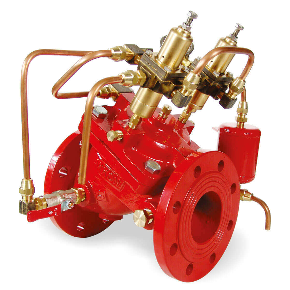

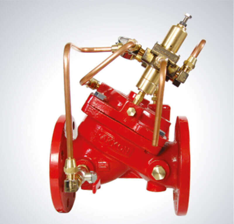
Surge Anticipating Control Valve
Control Valve Function:
Water Impact (Water Hammer) Prevention Control Valve 235 series
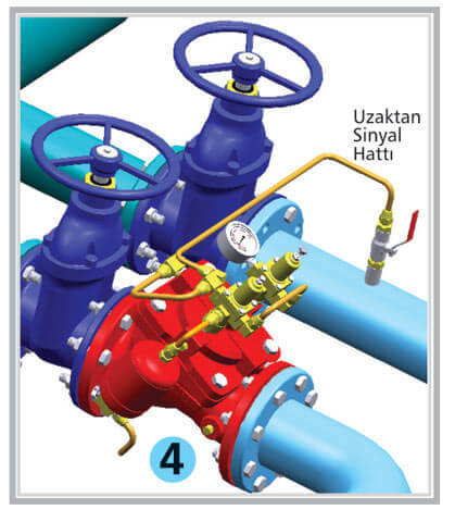
When pumps geometrically feed into a tank with a large quota, these valves protects the force main and its parts from ΔP water hammer changes in pressure caused by speed differential during sudden energy cuts where the pump starts irregularly. ΔP water hammer; happens when the pumps shut down or there is a power cut outage and the reverse flow gets trapped in front of the reverse flow preventing valve, and increases the pressure, turning the pressure into a pressure wave which pushes against the force main. The water hammer valve which has been attached to the force main directs this pressure into the atmosphere preventing it from damaging the fixture.Pressure change control is achieved by signal lines constantly sensing the water pressure and opening and closing the valve accordingly. There are 2 separate pilot valves to sense pressure increase and decrease within the control valve.

Surge Anticipating Control Valve Pilot Control Circuit:
☆ The pilot circuit works efficiently for extended periods due to a fully otomatic self cleaning ½” filter
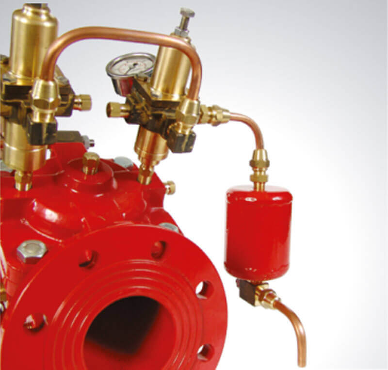
☆ The fittings in the control circuit are (½” automatic filter, ½” global valve as remote signal line), ¼” needle valve, as the pilot 2 2/2 multiport pressure control valve, manometer type with glycerine, accumulator, 3/8″ copper pipe and pounded brass pipe fittings.
☆ The pilot valve, made with pounded brass, has rustproof interior components.
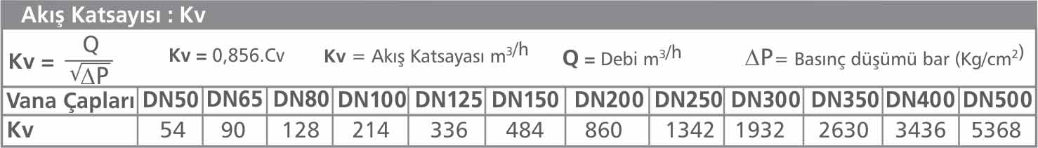
Determining the Water Hammer Valve Diameter:
It is necessary to calculate the Kv-t value of the force main before determining the diameter. When calculating the Kv-t it is important to base the Dp value on the pressure differential during atmospheric release. The valve Kv values would then be chosen close to the calculated Kv-t value.
☆
ΔP water hammer = a x v/g here ΔP water hammer : mSS
a: Pressure wave speed – m/s
v: Force main water speed – m/s
g: Gravitiy exceleration – 9,81 m/s²
☆
Reduction Pressure (mSS) : ( Dp = Hd – ΔP)
Increase Pressure (mSS) : (Ds = Hd + ΔP)
☆
Kv-t = Q / √Dp burada Kv-t : Force Main flow factor (m³/h)
Q: Force Main flow rate (m³/h)
Dp: Reduction Pressure (bar)
(Pressure differential at discharge into the atmosphere)
Application
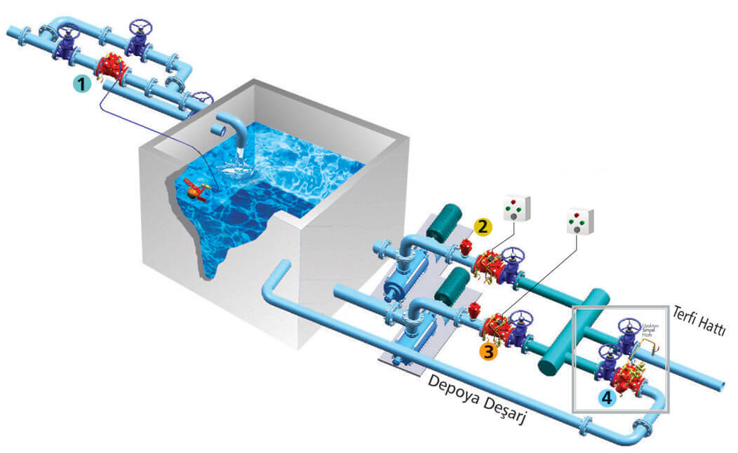
Fixture Assembly Details:

Surge Anticipating Control Valve Technical Details:
☆ 60º slanted half linear flow body suitable for attaching to a diaphragm type actuator.
☆ Body encompassing changeable bronze bushing.
☆ Single control type actuator.
☆ Diafphragm; polyamide court fabric knitted double layered neoprene rubber.
☆ The diapragm’s life has been extended indefinitely by passing it and the flap attached to it through a shaft to the upper lid which is housed in bronze bushing.
☆ The inner spring is centered from the exterior to the upper lid and flap, and attached to the upper control reservoir.
The wear resistant, rectangularly designed flap rubber is attached to a changeable flap.
☆ All control valve parts can be replaced easily without having to detach the valve body from the fixture.
☆ All valves are coated with wear resistant, kiln fired electrostatic EPOXY coating.
☆ All valves are submitted to hydrostatic and function tests.
☆ All control valves are protected against production and labor errors with a 2 year guarantee.